With more than 10,000 systems from one manufacturer installed worldwide as of 2021, the case for CO2 as a refrigerant is compelling.
CO2 as refrigerant (R-744) has over the past decade become more and more popular in food retail applications as well as distribution and storage, production and other types of facilities. To many current and potential users, it may seem to be a new alternative to the almost 100-years of reliance upon synthetic CFC, HFC and HCFC refrigerants that have dominated commercial refrigeration. But before these refrigerants became as widely used as they have been, CO2 was already in use.
Refrigerant List
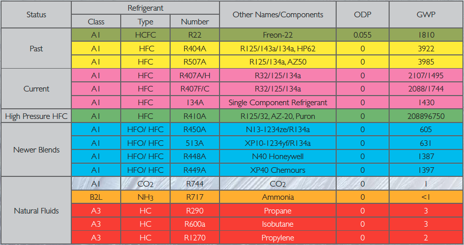
CO2 has long been known to have superior thermo-dynamic properties as an approved A1 refrigerant, and unlike most synthetics such as A3 refrigerants that include propane, or B2L refrigerants that include ammonia, is non-flammable and non-toxic. But while the higher pressures required for its operation were long seen as a potential barrier to its wider spread acceptance, in some ways that factor actually adds up to an advantage since it allows for higher volumetric capacity which in turn allows for more compact component and system designs. CO2 refrigeration racks (the metal frames and various components such as compressors, receivers and heat exchangers that make up the typically single largest pieces of equipment apart from condensers) compared to similar capacity HFC racks are generally smaller. Likewise, comparatively less refrigerant is needed for CO2 systems.
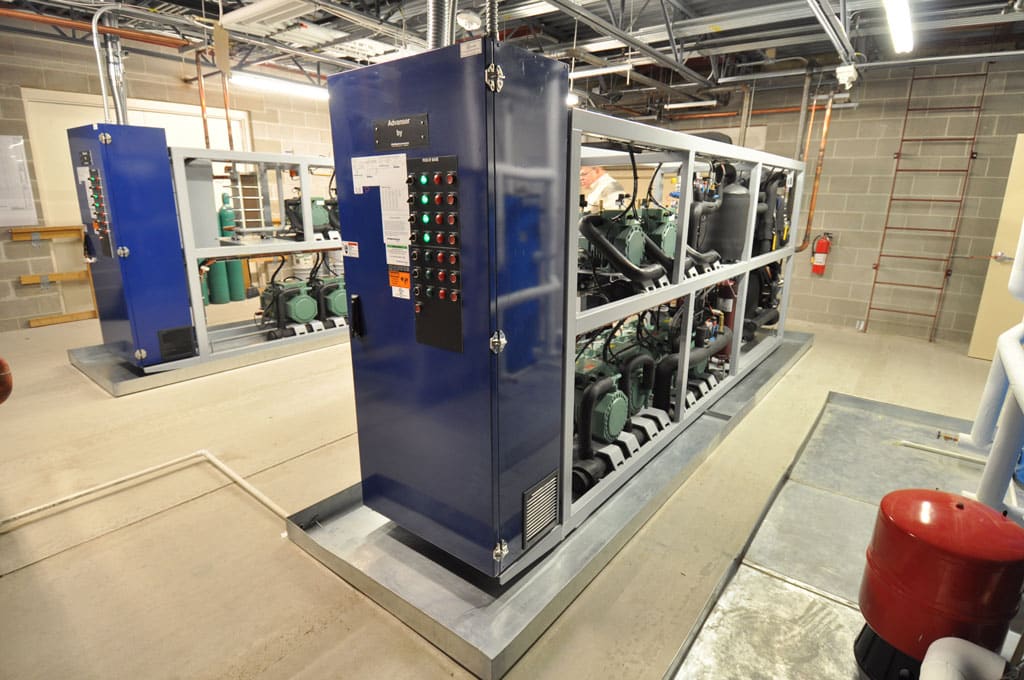
CO2 (R744) Refrigeration Rack
CO2 within the past dozen years began being commercially used as a secondary coolant for low-temperature applications. Eventually, new developments in the technology further led to its use as a low-temperature direct expansion (DX) refrigerant in cascade refrigeration systems. The difference between the two is that whereas CO2 used in secondary systems, circulates as a chilled fluid that absorbs heat without changing state, in a CO2 cascade refrigeration system it is used as a conventional refrigerant undergoing changes in state as it moves from one heat exchanger to another. What makes the latter approach a cascade system is that a heat exchanger connecting the upper and lower cascade is the condenser for the lower while at the same time also working as an evaporator for the upper. In other words, the upper section cascades its cooling to the lower section. Both of these approaches however, continued to rely on the use of HFCs in the primary side of secondary systems and in the upper section of cascade systems, albeit in far reduced volumes compared to conventional systems.
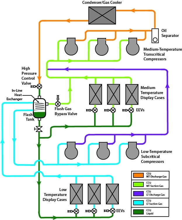
An All-CO2 Refrigeration System
Building upon the success of these advances, starting in Europe the industry finally began adopting the use of CO2 as a sole refrigerant in food retail and other applications. This approach, using what’s known as a booster system, leverages the advantages of CO2 to deliver a more efficient sustainable and ultimately less costly approach to refrigeration.
 A CO2 booster system instead of using an HFC for the primary side of the system and CO2 for the lower side uses only CO2 for the entire system, both for medium-temperature and low-temperature loads. It is able to do this by virtue of some significant advances in technology that take advantage of the thermo-dynamic properties of CO2.
Prior to the development of booster systems, major challenges to the use of CO2 as a DX refrigerant stood in the way of its acceptance. These obstacles were mostly a consequence of the relatively high-pressures that such a system would be required to operate at. These difficulties were overcome by the development of certain key components now commonly used in booster systems – among them a special type of high-pressure control valve, CO2 condenser (gas cooler) and use of high-pressure copper piping.
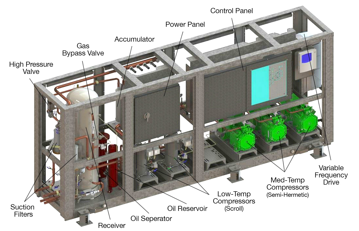
Apart from these two parts of the system, most other aspects of CO2 booster systems are familiar to anyone who knows how traditional DX systems work. Like those, booster systems also have the four main components that include compressors, evaporators, expansion valves & CO2 condenser (gas cooler). The difference is that these components are rated for higher pressure and that in place of mechanical expansion valves, electronic versions, and case controllers for evaporator temperature control are used.
Another key difference from other types of DX systems is that booster systems work with the same refrigerant moving between the low- and medium-temperature compressors. The low-temperature compressors are subcritical as they discharge to the suction of the medium-temperature compressors which are transcritical as they discharge to the ambient. In other words, the low-temperature compressors serve as a booster to the medium-temperature compressors. This may seem like a similar approach as the cascade refrigeration system described above but instead of one system with two different refrigerants, a booster system only has one. This point is worth emphasizing: a CO2 booster system uses only CO2; there is no other type of refrigerant in the system.
A CO2 booster system is also referred to as a transcritical refrigeration system meaning that its operation transfers from a subcritical to a supercritical state depending on the ambient conditions such as when the outside temperature reaches 88°F, the refrigerant exceeds its critical point. From here on, the ambient air does not allow for all of the heat in the refrigerant to be removed until the pressure and temperature drops below that point. The only way to reduce the heat load of the refrigerant is to
release as much of it as possible to the outside air, and this is also why under these conditions the condenser is referred to as a gas cooler since it is cooling the gas as opposed to fully condensing it.
Enthalpy – P-H Diagram
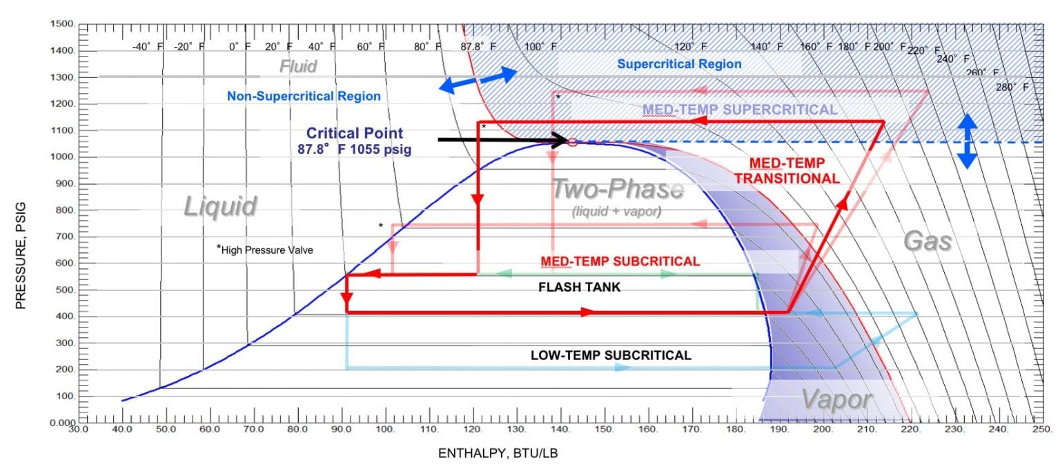
In the booster system, low-temperature subcritical CO2 compressors operate at around 200 psig, well below the critical point for CO2 receiving suction gas from the low-temperature display case and freezer evaporators. The low-temperature compressors then discharge that gas at about 425 psig combining it with the medium-temperature suction gas from the medium-temperature display cases and walk-in cooler evaporators before entering the medium-temperature transcritical compressors. Medium-temperature discharge gas leaves the compressors, depending on ambient conditions, anywhere from 560 psig to as much as 1450 psig, which is above the critical point of CO2 at 1070 psig (at 88°F). Under warmer conditions in which the pressure rises above 1055 psig, the system operates in the transcritical range.
Under any conditions, however, the discharge gas from the medium-temperature compressors feeds to the gas cooler, where the heat it carries is rejected to the outside environment. This heat rejection process is standard in any refrigeration system.
The CO2 leaving the condenser feeds to a high-pressure control valve that controls the pressure in the gas cooler, similar to a traditional hold back valve that allows a pressure drop to assure some liquid CO2 refrigerant flows into an intermediate pressure receiver called a flash tank (a high-pressure tank similar to a traditional receiver). The gas enters the valve from 560 to 1450 psig, depending on ambient conditions, and regardless of those conditions exits the valve at 540 psig. The valve is designed to work somewhat like a holdback valve in order to maintain optimum pressure through the condenser when it is working as gas cooler for the most efficient operational performance of the system.
The flash tank works the same way, in principle, as a component used on most types of refrigeration systems that’s called a receiver. This is usually a vessel that contains all of the refrigerant charge of the system when needed such as during maintenance or if the system ever has to shut down. The pressure in the tank is held at a constant level that is sufficient to maintain differential pressure throughout the system.
From the flash tank, where both liquid and gas can be present, the liquid refrigerant is supplied to the medium- and low-temperature evaporators controlled by conventional electronic expansion valves. Vapor from the flash tank is fed through a flash gas bypass valve (another specialized component) back to the medium-temperature compressors. The flash gas bypass valve maintains a constant pressure in the flash tank and removes the gas buildup in the flash tank.
Apart from some of the special components just described, the system works similarly to other types of DX systems. The main differences are related to the two-stage design of the system and the fact that all evaporators in the system are supplied with liquid from the same source. For most experienced technicians, the system will not seem overly complicated.
CO2 Refrigerant Benefits
Besides the simplified basics of the system, CO2 as a refrigerant offers a number of advantages. These have to do with material and equipment costs as well as installation and operation costs not to mention sustainability and the benefits of regulatory compliance.
Simply looking at the use of CO2 refrigerant from a cost basis, underscores the point. A supermarket that switches to a 100% CO2 system will save money on refrigerant charge. In one example, a supermarket saw immediate benefits from installing a CO2 booster system with a low-temperature refrigeration load of 200 MBTUH and a medium-temperature load of 650 MBTUH. The store needed an initial refrigerant charge of 2,000 pounds of refrigerant. Using an HFC-based refrigerant such as R404A for example, would cost $8 per pound (newer HFO refrigerants such as R448/449 can be as high as $12 per pound). But CO2 refrigerant by contrast costs around just $1 per pound. Using CO2 instead saved that store $10,000.
CO2 ROI Summary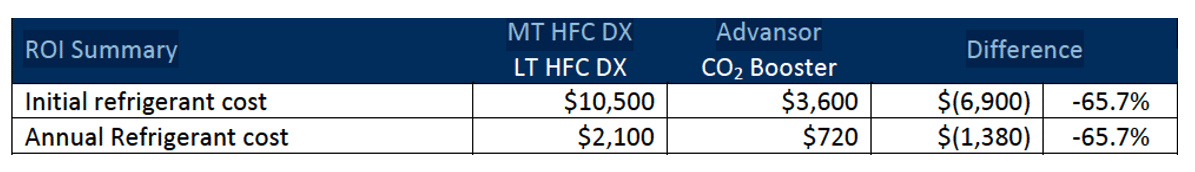
This particular store located in the southeastern United States, furthermore, represented something of a breakthrough with the first warm-climate CO2 booster system. Prior to its installation, these systems had largely been limited to cooler more-northern climates due to the thermo-dynamic properties of CO2. With the application of a particular type of condenser called an adiabatic condenser, a long-standing technological (and effectively geographical) barrier to more widespread use of CO2 was overcome.
Another benefit CO2 offers is in energy savings. A 50,000-square-foot supermarket can spend more than $200,000 annually on electricity, half of which goes toward refrigeration, according to the U.S. Department of Energy. CO2 refrigeration systems, however, can operate more efficiently than their HFC counterparts. Supermarkets can save from 5% to 18% on energy bills, depending on their location and source of power.
As might be expected, the specialized valves, compressors and electronic controls used in a CO2 booster system can raise the cost of equipment, compared to a traditional HFC system. But the cost of CO2 equipment is following the same pricing pattern as any new technology—new technology gets less expensive as more users adopt it.
Installation costs, on the other hand are consistently lower with CO2. Due to the higher volumetric capacity of CO2 smaller copper pipe sizes can be used which lowers material costs. And the smaller line sizes in CO2 systems are easier to install, which further lowers labor costs. Overall, users can expect savings of 12% to 18% on CO2 installation. Consequently, and perhaps most crucially, a lower total installed cost (i.e., equipment & installation) along with reduce refrigerant charge, does impact the total cost of ownership.
Other benefits of CO2 extend to one of the most immediate challenges facing users: regulatory changes with the cost and risk associated with compliance. In light of the pending phase out of HFCs, food retailers continuing to rely on them are only going to see their costs rise. CO2 systems provide a natural refrigerant solution that helps future proof business by eliminating the need for refrigerant retrofits and the burden of complying with current and future regulations.